Long Live The All American Five. Or, Recovering a Piece of Radio History
“Watching” the Radio
Right now, in 2009, radio and “wireless communication” is ubiquitous and part of the landscape. As such, no one really notices it. It is a taken for granted reality of everyday life.
 It’s hard for modern people to put themselves in the position of people in the early 1900’s when radio was a new invention. Imagine, hearing voices and music from across the country, or across the world – without wires. Instant communications. You don’t have to wait for the newspaper to find out what was going on. Entertainment? Sure. Turn on the radio and hear Burns and Allen, Jack Benny, The Great Gildersleeve, The Inner Sanctum, Sam Spade, The Shadow, GI Journal, and hundreds more.
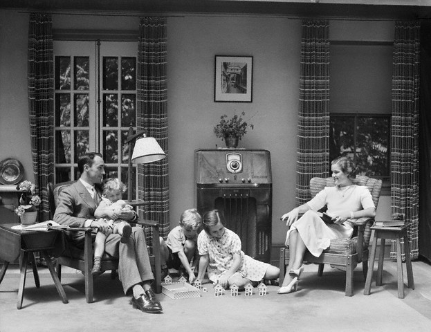
It’s always interesting see pictures from the 1930’s and 1940’s of a family sitting in the living room “watching” the radio. Watching the radio as if someone was talking directly to them – from hundreds or thousands of miles away. And that is exactlywhat it was – astrounding.
Recovering the Past
I can only imagine that some folks who collect old broadcast radios have some sort of appreciation for this era. When you get that radio from the 1920’s to 1940’s one can imagine how many families sat in front of that radio listing to music, news, or entertainment. Perhaps, in 2009, that family has passed away. But the radio, which you have in your hands right now, just may remember. On that radio from the 1940’s perhaps they heard the call to buy war bonds. Or, that was the radio on which they heard the start of the D-Day invasion, or the end of the war.
So, that “junk” tube broadcast radio that you see at the flea market or hamfest may have a story to tell. Why not give it some life? If it’s ailing, perhaps all it needs is some TLC (Tender Loving Care)
Preparation
Before you do any surgery on that radio perhaps you need to get yourself up to speed on internals of these delicate pieces of history. Many of these radio are easy to fix – if you have some basic knowledge of how these radios work.
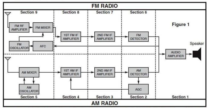
Generic AM/FM Block Diagram
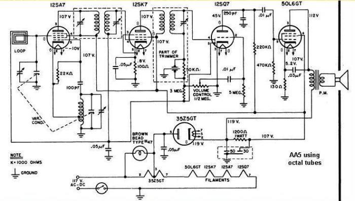
Generic AA5 Schematic
Quick Overview
Inexpensive Tube broadcast radios from the 1930’s, 1940’s, and into the 1950’s are all basically the same design.
The design was known as the “All American Five”. The “Five” from the tube lineup in these radios. The standard generic AA5 radio tube lineup represented the steps to take the RF from the “air” and get it into audio that you can hear.
The AA5 tube lineup was: Converter(Mixer), IF Amp, Detector, Audio Amp, and Rectifier. Some radio had more or less tubes. For example, some radio also had a RF Amp, Push/Pull audio, and pre-amp. So you could have more or less tubes than the standard AA5 radio design. But, the bottom line, all these radios were basically the same – clones of each other with minor improvments or cosmetics.
An excellent site on the AA5 can be found here. http://home.netcom.com/~wa2ise/radios/aa5h.html and here http://pweb.netcom.com/~wa2ise/
Hands-on Electronics
Danger – High Voltage
Perhaps before you get your hands into that antique tube radio with 100+ volts swirling around in there you might want to learn something about radio “hands on” by building a simple AM radio with transistor.
The basic “get” is this. The strategy of getting an RF signal off the air and into audio that you can hear is still the same after 60 years. If you build a kit transistor AM Radio you will get much of the knowledge that you will need to understand these AA5 tube radios from the 1930’s-1950’s to the point that you can troubleshoot them and fix them.
No Danger – Low Voltage and “Learn as you Build”
Elenco has an inexpensive AM radio kit specifically designed for educational purposes. That is, unlike Heathkit radios of the past, which in my opinion, was “outsourced manufacturing to the hobbyist”, the Elenco kit is “learn as you build” – there is an specific and direct educational goal.
The learn as you build strategy is basically this. Present the theory, build the practical part of the radio, make test measurements to ensure the section works and validate the theory, and then integrate into the rest of the radio and do a system test of the integrated systems to see how all the parts work together.
To get full advantage of learn as you build, you really need a scope – at least. If you have a RF signal generator, frequency counter, and scope – then you are all set.
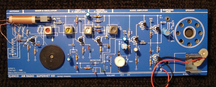
The Elenco AM Radio kit.
The picture below is a kit from the late 1980’s. Elenco still makes a kit similar to this but it uses an IC (LM386) for the audio amplifier section. My kit has a few transistors for this. Doesn’t matter. The modern kit will do just fine.
The Elecno AM radio kit is build in 6 sections back to front
- Audio Amp
- Detector and AGC(Automatic Gain Control)
- Second IF Amp
- First IF Amp
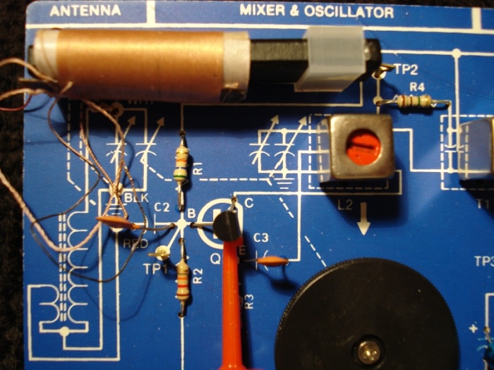
- Mixer and local oscillator
- Antenna section
The cost of the kit is about $25 (AM only) to $40 (AM and FM)
You build and test each section and as the radio is constructed- back to front – you continue to build and test until the final section is completed and you hear the radio actually working. Since the construction strategy is: build, measure/test, and integrate is is nearly impossible to fail at having a working radio at the end.
The picture of the components and the sections on the board helps you place the parts and shows you the logical sections of the radio – as a help to understand the process of developing the audio from the RF.
Now apply this to the AA5
You will see that all these sections in your transistor low voltage kit have direct parallels in the AA5 – a standard configuration from the 1930’s to 1950’s in inexpensive tube radio receivers of that era.
If you can understand how this Elecno kit works then you should be able to understand how the AA5 works. The strategy of developing the audio from the RF signal is that same. The only difference is that the AA5 uses tubes where the transistor kit uses transistors.
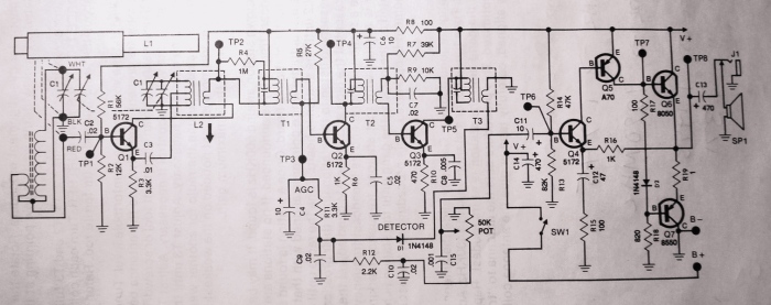
Take another look at the generic AA5 Schematic and the schematic for the Elenco Kit
Look familiar with the Elenco kit and the AM block diagram? It should.
- The first tube in the AA5 is the 12sa7 tube. This is the Mixer. On the Elenco kit the mixer is transistor Q1. The mixer takes the tuned RF signal and mixes it with the local oscillator to get a 455KHz Intermediate frequency.
- On the AA5 the next tube is a 12sk7. This is the IF amplifier that takes the 455 KHz IF amplifies it and passes it on. The Elenco kit has two stages of IF amplification. This is Q2 and Q3.
- Next in the AA5 is the 12sq7 tube. This is the detector and first audio stage. On the Elenco detection is done by a solid state diode. The principle is the same. The diode and associated capacitors recover the audio from the 455Khz IF.
- Next in the AA5 is the 50L6GT tube. This is the audio amp. On the Elenco this is Q4,Q5, and Q6. Done with transistors the principle is the same – amplify the audio.
- The last tube in the AA5 is the rectifier – the 35Z5to convert AC to DC. The Elenco runs off 9 volts DC supplied by a battery. So no rectifier is needed.
At the very front of the radio is the mechanical tuning capacitor. Both the AA5 and the Elenco use the same principle of an air dielectric capacitor. Both radios have basic circuits called AGC (or AVC) automatic gain control that controls the gain of the IF stage based on the strengh of the signal at the detector to keep the signal (audio) at a constant level as you tune across stations. Both radios have coils and a ganged tuning capacitor for the local oscillator. The ganged tuning capacitor makes it possible to keep the local oscillator at 455KHz above the frequency tuned by the antenna tuning section.
Got the picture? These radios, in principle, are the same. If you can understand the low voltage transistor version you should be able to apply this to just about any tube radio built from the 1930’s to the 1950’s. The benefit of actually building the Elenco kit is “learn as you build”.
Using your test equipment to check things out
In the Elenco kit you will do some signal tracing, alignment, static and dynamic measurements. This is the same process in principle that you will use to diagnose problems or faults in your vintage broadcast reciever. The essential thing to remember is that where the Elenco kit uses 9 volts, your AA5 tube radio is using 100+ volts. Learn on the Elenco kit as prep for AA5.
Here are a few tests points on the Elenco. You would do the same on the AA5 as part of the troubleshooting and alignment process.
Check the local oscillator
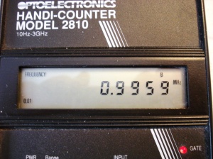
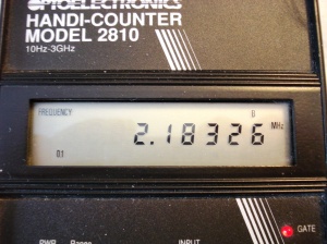
Checking the range of the local Oscillator. Using a frequency counter you can check the range of the local oscillator. The mixer (tube or transistor – also called the “converter) will mix the tuned RF with the local oscillator to get the difference frequency of 455 KHz. The tuning capacitor is ganged. That is, its really two tuning capacitors in one which turn at the same rate when you move the radio tuning dial. Keeping the antenna circuit resonant with the oscillator is called tracking. You want the oscillator to be 455 KHz above the antenna tuned frequency end to end for the tuning range.
My local oscillator tunes 996 KHz to 2.18 MHz.
So that means the radio tunes the broadcast band (996-455=) 540 KHz to (2180-455=) 1725 KHz.
Cranking the tuning dial full counter clockwise and then full clockwise got these frequencies.
Check the Intermediate Frequency (IF = 455 KHz)
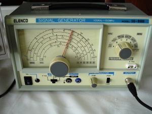
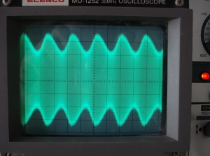
You will need a Signal Generator for this. Inject the signal on the Elenco at the First IF and see what comes out of the Second IF into the Detector. This signal generator generates a modulated AM signal at 1000 Hz. That is, an RF signal at 455KHz with a 1,000 Hz audio signal riding on the RF.
What you see on the scope below is a 1 KHz audio tone riding on the IF of 455 KHz
Check the detector
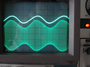
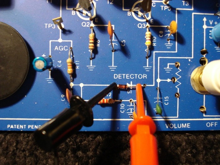 The detector (tube in the AA5 or solid state diode in the Elenco) along with capacitors recover the audio signal from the 455 KHz IF. The diode takes only the top of the signal above and then passes it through a filter that removes the high frequency IF and just leaves the audio signal ( 1,000 Hz tone)
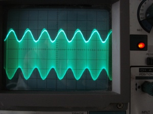
The scope is in dual trace mode. The pictures below show the signal before and after the detector. On the picture on the right I moved the audio signal over the IF so you can see how the audio is recovered from the modulated IF.
Test from the IF all the way back to the Audio amplifier
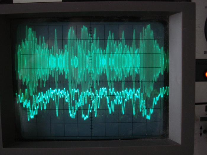
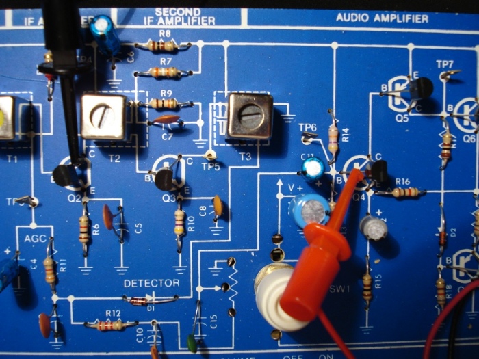 The final image is the dual trace with the radio tuned to a real broadcast station.
The image on the top of the scope is the IF with Audio.
The lower image is the recovered speech from the radio station.
The test points are from the IF through the detector and into the input of the audio amplifier.
Conclusion
 If you see that old radio from the 1920’s to 1940’s at the flea market or hamfest maybe it has a story to tell. It is quite possible that a family sat in front of that radio and listened to radio shows like Bob Hope, Burns and Allen, Sam Spade, The Shadow, and many others. Perhaps that radio was the radio that a family – now passed away – listened intently to the first reports of the D-Day landing or the end of the war in Europe.
Broadcast radio into the Shortwave bands is alive and well even today in 2009. So, why not pick up that old radio at the flea market for $20-$75 and give it some new life.
Most tube radios built during the 1930’s and 1940’s are the same basic design called The All American Five. Fundamentally, they are all the same. The technique of getting RF into Audio is still basically the same.
As prep for troubleshooting, repairing, and restoring that old radio why not brush up on a bit of radio theory and design. The least risky way to start without getting zapped with 100+ volts in a tube radio is to build an AM radio kit. These kits, using transistors, and low voltage are a good way to brush up on how radios work. Many of these kits are “Learn as you build” kits which will teach you about radio receiver design while you build the kit. It is almost impossible to fail to get a working AM radio at the end of the build process given the technique of theory-build-test-integrate.
If you can built one of these AM radio kits, and you have some basic test equipment like a Scope then you can apply this knowledge to troubleshooting and repairing one of these old AA5 radios.
The AM radio kit mentioned in this posting is good for kids if they show any interest in radio. The AM radio kit is only about $25. That is a small price to pay to facilitate a kids interest in electronics – if they show this interest.
In any case, pick up that old radio and give it a second life – you have a piece of history that should be preserved.
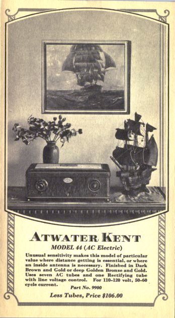
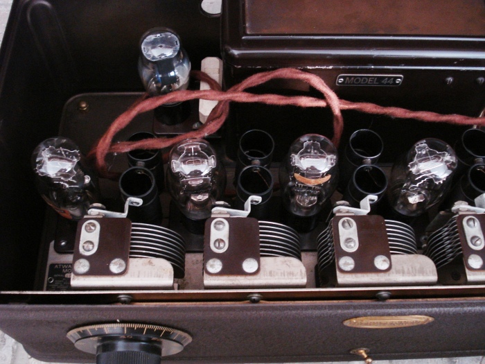
The oldest radio in my collection (so far) is a restored Atwater Kent model 44 shown below. The model 44 was made in 1928 and is still working 81 years later in 2009. I wonder who that family was in 1928 that bought this radio and what they heard. In the 1920’s it must have been exciting for them – they were standing at the dawn of a new age – the age of Radio and wireless communication.
Resources
Probably one of the best free resources on restoring old broadcast radios
The title of the book is The Vacuum Tube Shortwave Radio: Understanding and Troubleshooting.
The author is Richard McWhorter.
The book is 212 pages in length provided as a PDF.
You can read and print this book – the password is “allamericanfiveradio”
Thanks much Richard for making this available for free !!
The Vacuum Tube Shortwave Radio: Understanding and Troubleshooting by Richard McWhorter
Online Antique and Vintage Radio References
Thousands of schematics plus forums for technical discussions on vintage radios
http://www.nostalgiaair.org/
Old time Radio programs
12,000+ Old Time Radio Programs in streaming audio – http://www.otr.net/
Pictures of classic radios
http://radioatticarchives.com/
http://www.atwaterkentradio.com/
AM/FM Radio Kits to purchase
http://www.ciebookstore.com/bookstore/catNo/52/productid/159/addtocart.asp
http://www.abra-electronics.com/products/product.php?productid=845&cat=69&page=1
This is the “Learn as you Build” manual from one of the kits above
Background on the AA5 Design
http://home.netcom.com/~wa2ise/radios/aa5h.html
http://pweb.netcom.com/~wa2ise/
Relative value of US Dollar over time
In 1926 the Atwater Kent model 44 cost $106 minus tubes. How much is that today?
http://www.measuringworth.com/uscompare/?redirurl=calculators/uscompare/
Current data is only available till 2007. In 2007, $100.00 from 1926 is worth:
| $1,171.42 | using the Consumer Price Index | |
| $987.44 | using the GDP deflator | |
| $2,496.88 | using the value of consumer bundle * | |
| $3,997.56 | using the unskilled wage * | |
| $5,534.72 | using the nominal GDP per capita | |
| $14,242.00 | using the relative share of GDP |
I learned my electronics in USN A and B schools, in 1970, they were still teaching vacumr tubes. Good education. All of what you say is true. We used a ref gen, and a vtvm to test and align radios what a pain trying to align an IF. Out of 40+ weeks of school 1 week devoted to transistorrs. Joe
Joe
October 13, 2015 at 10:14 am
Atwater Kent did build superheterodyne radios such as the 82 and others. You can look at the schematics on the nostalgiaair website to verify this. I did not look at all of the schematics, but it does seem that they used a power transformer and thus while being superheterodyne were not of AA5 garden variety.
Klondis
August 17, 2013 at 12:11 pm
Atwater Kent radios were never AA-5’s. Actually Atwater Kent refused to build AA-5’s and this decision contributed to the demise of AK. AK only built TRF (Tuned Radio Frequency) transformer or battery operated sets. All AA-5 sets were (are) superheterodyne ( the superheterodyne concept was developed by electronic engineer genius Edwin Armstrong who also later developed “Armstrong FM,” today commonly referred to as just plain FM. The AA-5 could be considered among the first execises at what we now call “value engineering.” The AA-5 gives fully credible performance with minimum components. However, the elimination of the heavy and expensive power transformer in the AA-5 was a real engineering coup at the expense of safety. It is advised, for this reason, that an isolation transformer should be used to reduce the risk of electricution when servicing AA-5 sets. A 60 watt isolation transformer should suffice as the average wattage for these sets was (is) about 30 watts. Most of this power goes to heat the tube cathodes as the average audio output in watts hoveres around 1.5 watts. Always think and understand safety first.
Roland Petit
February 19, 2013 at 8:00 pm
Thanks for the reply. Once something becomes a commodity it seems it’s competition on price alone. I at least put a polarized plug on some of my old radios – but that still does not make it safe, as you point out. I have a couple of S-38 Hallicrafters. They have a metal case and the only thing between the chassis and the metal case are washers. Once those washers disintegrate due to age then the chassis and the metal case are one. I much prefer the bakelite radios or wooden radios. Too bad the days of “radios as furniture” went the way of cheap metal or plastic cases.
frrl
February 24, 2013 at 11:58 pm
This is a Great article! I spent much time as a youth in front of a Zenith TransOceanic, and proud to say I still have it! I am building the Elenco AM kit at this time, and your information about this kit is very helpful! Thank You!
Tony T.
November 8, 2012 at 9:37 pm
Hey! can i ask a qquestion. I have a similar project and i dont know how to connect the antenna oscillator section. since i have the “miniature tuning capacitor” included in the kit. does it need to use the jumping wire though?
Thanks!
elexstudent
July 27, 2011 at 1:54 am
nice article. I found a 1960 Toshiba AA5-style radio for 1.99. Cleaned it up, replaced a few components, voila amazing sound quality from its little speaker. By the 60’s radios like this one were using the miniature tube setup, but still sounds great to me.
Jules
April 22, 2011 at 8:50 am
it has been quite sometime and the interest is still there;radio-electrons–all amazing stuff.thanks to your site i am going to get back into a very interesting electronics of the past. only as a hobby.already bought an old time radio in a wooden box yes it has a problem going to go at it slowly if i can remember the stuff as i had known it—thanks for getting me to the right door. wiskers
ken hudson
July 1, 2010 at 12:50 am
nice article on radios and links. I work on old radios as a hobby.
Steve
wv2lkm
steve
February 22, 2009 at 6:12 pm